ESP32 MP3 Player
Description
TouchMP3 is a DIY MP3 player I’ve been building from scratch. It’s powered by an ESP32-S3 and uses a touchscreen for control instead of buttons. The goal is to make something that feels like a modern device, but is completely custom-built and designed at the PCB level.
I wanted this project to be more than just “play music.” With the parts I’ve chosen, TouchMP3 can handle audio playback, recording, and charging, all while staying compact and portable.
Images
Check in the images folder for all the images
Project Features
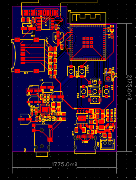
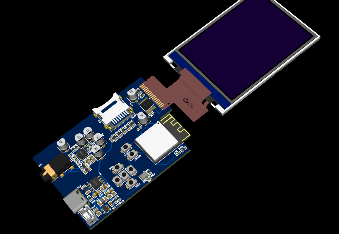
- ESP32-S3 – The brain of the MP3 player. Handles audio decoding, Bluetooth (future feature), and touchscreen input.
- Touchscreen + Touch Controller – No buttons, just direct touch control for menus and playback.
- ES8388 Audio Codec – Provides high-quality stereo audio output and integrates well with the ESP32 for I²S.
- ICS-43434 Digital Microphone – Allows basic voice recording or other mic-based features.
- Headphone Jack – Standard 3.5mm jack for wired headphones.
- USB-C Port – For charging and possibly data transfer later on.
- TP4056 Charger IC – Manages charging the lithium battery safely.
- LDO (Low Dropout Regulator) – Keeps the ESP32 and audio components powered at a stable voltage.
Installation Guide
Right now, there isn’t any software to install yet. Once I start working on the firmware, I’ll add step-by-step instructions here for flashing the ESP32-S3 and loading music onto the device.
Journal
The main creation phase of the PCB was not journaled so well, but I used EasyEDA for the PCB. I use the Hack Club Grounded grant to fund my PCBs. YOu can see the main features above, but this section will shows my main challenges with getting the PCB to work.
10/11/2025 - Attempted to troubleshoot device not being recognized
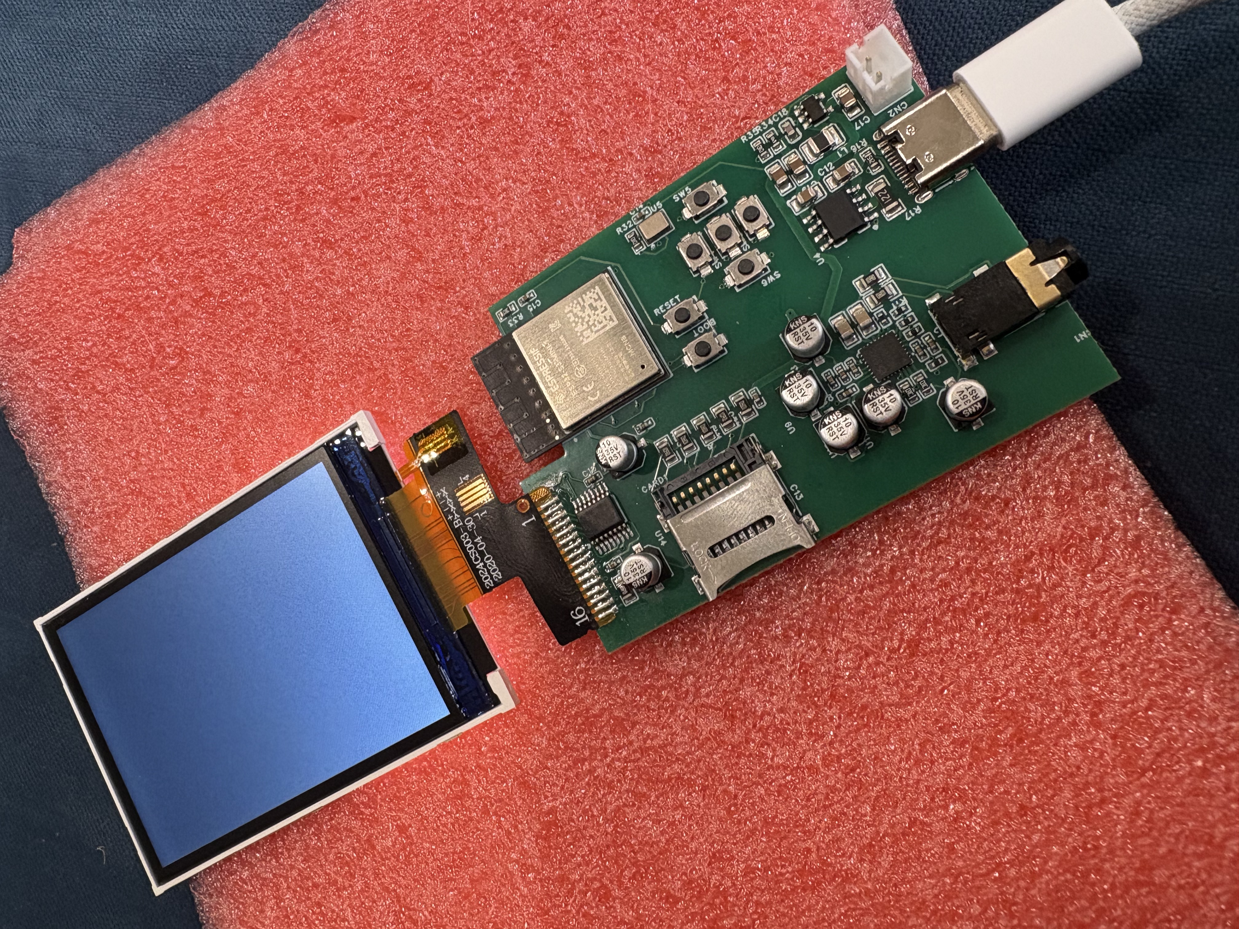
So I got the pcbs and I was so excited. I plugged in a cabe that I knew supported data transfer and I saw that the screen backlight turned on! The next thing I did was to check if the device could be recognized by my computer. My Mac couldn't recognize it even after I tried both directions, entered boot loader mode, tried every combination of boot and reset I could find online, checked if the esp32 was being powered (it was), trying every single usb-c cable in my house, and even testing it out with a windows computer. I searched through so many forums and they all had some different problem going on with theirs, so maybe I will try asking for help on credit of some other forum. I also realized that I only placed a 5.1k resistor on the cc1 of the USB Port and not both, so I may have to add another or the usb cable will only work in one direction. Also I din't think I made the d+ and d- lines the same length which is a huge problem that may be the reason my pcb is not working. Here is picture of the boards that showed up.
10/12/2025 - broke both pcbs D:
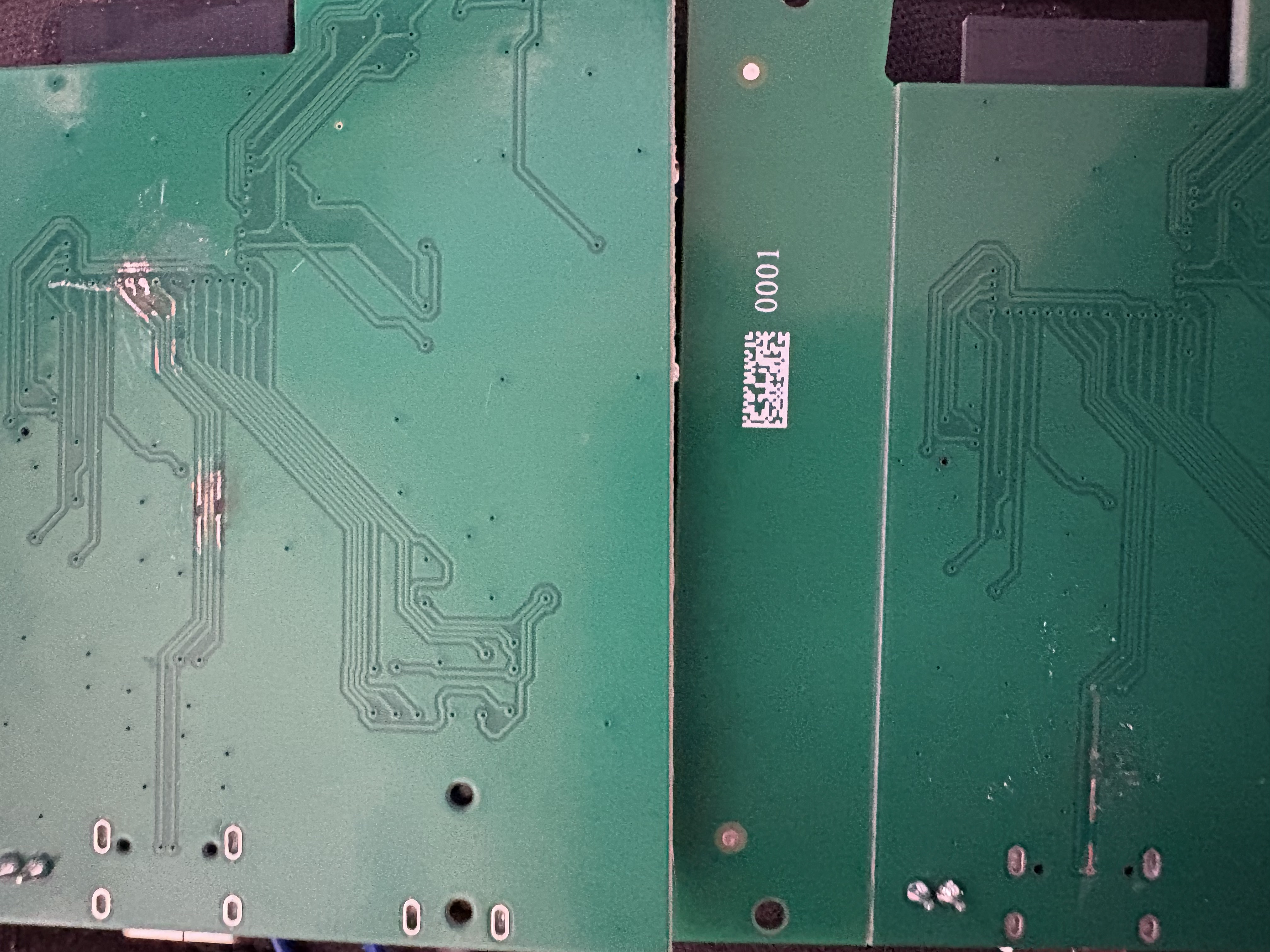
Uhhhh... So today started of great, I made a post on credit asking for help and while I was waiting I found the issue. my dum ass router D+ and D- to the wrong pins on the esp32. That is quite possibly the stupidest mistake to make, and I was feeling pretty bad, but someone suggested scraping off the wires and connecting the D+ and D- to the right pins. I took my boxcutter, removed the blade, and slowly practiced scraping off the solder mask on the unassembled pcbs to practice. After I got it down and soldered on a thick insulated wire (the only one on hand), I moved to the real deal. I was way to ijmpacient, so I scraped off the solder mask at the right spots, and realized that the connection distance was so short (they were right next to each other) that I could just connect them with a solder blob. So I did that. Esp32 still not recognised :(. I decided to take a spare full sized usb from some other board and connect it to the board at the right spots since I thought the usb-c was the issue. My idea was that since I have a micros card slot on the board, I could quickly make a script that read the card and did the code written on their instead of me having to reflash the memory with my makeshift port. So I soldered on 5v and gnd. So far so good. then I soldered on the D+ wire, still looking pretty good. Then I accidentally moved the board, and I saw the D+ wire come offf the board, carrying the trace with it. Since I connected it at the very very edge of the esp32, I couldn't just rescrape another part of the trace. I feelt really bad, but at least I had another board, right? Spoiler alert: Even with trying to use special thin solid core wire I also retire the trace. But this time it wasn't at the very edge of the board, so there is still a way to salvage the board. I am thinking the next step forward is to order another board (not assembled) and then desolder and solder all the components not the new better board. I have never done manual assembly on such a small board before with SMD components, but with a hotplate and stencil, it shouldn't be that hard, right? becides a new set of 5 pcbs is only 3.72 dollars more.
11/2/2025 - bought another pcb
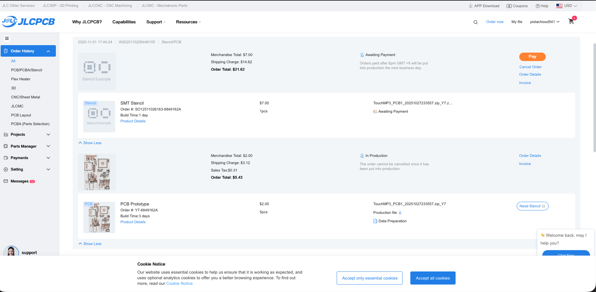
I rerouted a few traces, added a spot for a resistor, and submitted the board to JLC PCB. The total price was 5.80 so I just payed myself. After doing this, I realized that if I wanted to transfer the components by hand, I would need a stencil. Thankfully, jlcpcb had a button so I could order one. But with shipping it costed 20 bucks, about 20 more than what I wanted to spend. But I have an idea. I can use a cnc router (at the library) to make my own. I just need a thin material and a tiny bit, right?
11/30/2025 - tried soldering on components to the new PCB
So the boards arrived, and i picked up some soldering paste from amazon to solder on the components. To do this i applied a thin layer of flux along the board, added solderpaste manually to the pads, and then placed the components I desoldered from the old PCB on the board.
Now to solder all of these, I thought i would be smart and use a stove. I heated the pcb on aluminum foil over the stove and I saw the components fitting into place. but, the fumes got prety bad and the flux was burning
After testing this PCB, i found out it still did not work, so I went back manually and tried fixing some of the connections with my soldering iron. The work was tedius and the burnt flux was turning the white PCB board black and sticky.
I still could not get the boards to work, and after fiddling around with even more solder, components were starting to burn and I was afraid that I had burnt the ESP32s.
Conclusion
So, ultimately I never finished this project, mostly because the components were smaller than grains of sand and I had other projects (such as the science fair) going on at that moment.
But I learned a lot from this project. I learned how to assemble PCBs with SMD components, how to use soldering paste, how to design complex PCBs, how to seperate analog and digital components, and it was also my first project using Hack Club Grants.
I still am intrested in making a new version of this PCB that maybe isn't quite as ambitious and I can make for cheap. It would be really cool!