A Spin on Air Pollution: Science Fair Project
Science Fair Log
A Spin on Air Pollution: Optimizing Cyclone Separators as Low-Pressure HEPA Pre-Filters
12 / 10 / 25: Started Brainstorming Ideas for Project
OBJECTIVE: Today I started brainstorming topics I could run a scientific experiment upon. I used several methods for this including Wikipedia brain maps, asking people, and building off of personal struggles.
First, I followed a commonly used brainstorming method called mind maps. I started on a page in Wikipedia I was interested in (computers) and started clicking interesting hyperlinks. Over time, I slowly gravitated toward topics that interested me. I started with several different words (Plant, Internet, Pollution, Natural Disasters, etc.) And ultimately found that AI, air pollution, computers, and neuroscience were gravitated to particularly.
Next, I asked people around me for input on what they would like tested or fixed in the world. Many talked about natural disasters / environmental concerns such as floods, earthquakes, ocean pollution, and air pollution.
Lastly, I pondered on my own personal struggles, and suddenly, it hit me: whenever I travelled to India, I would always develop illnesses, coughing, and eye irritation from the intense air pollution in the New Delhi area. I decided air pollution would be an umbrella topic for my project.
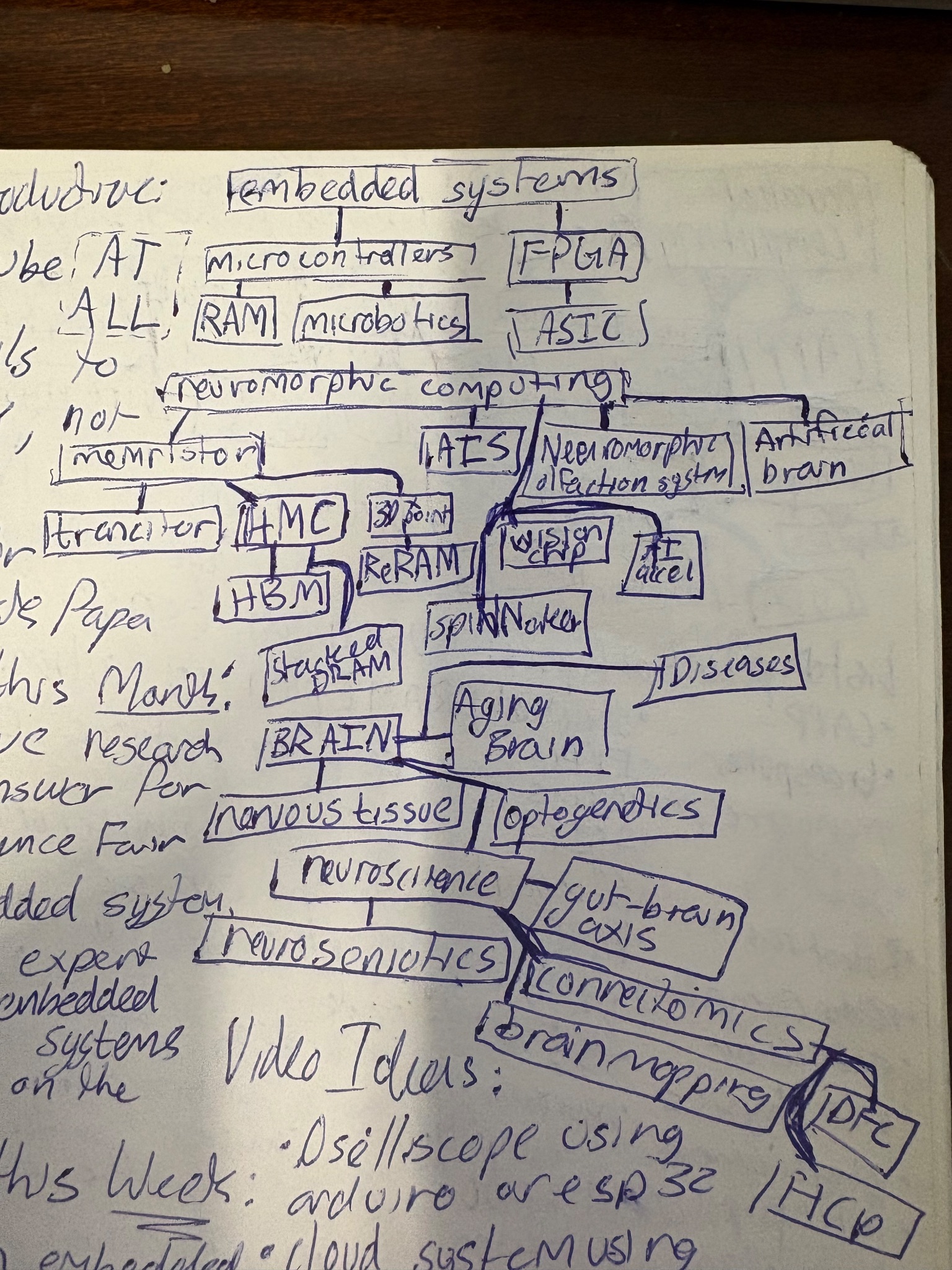
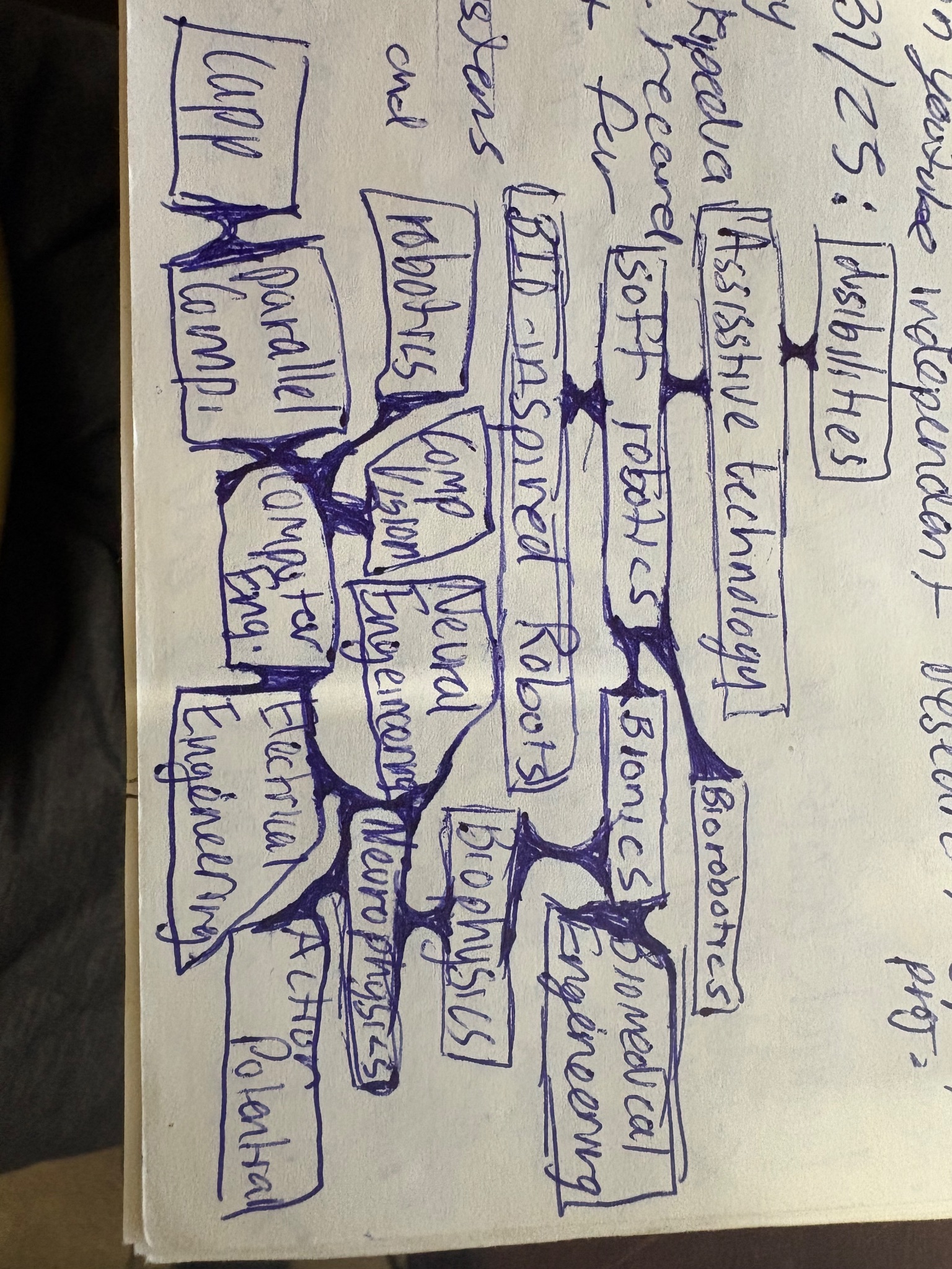
**NEXT STEPS: **Develop a testable research question around air pollution
Picture of mind maps
12 / 28 / 25: Developed Idea
OBJECTIVE: Over the past two weeks, I spent a long time researching gaps in current air pollution prevention techniques.
I used sources such as Google Scholar which was able to show me reputable research on this field. After many days of searching I found a type of inertial filter called Cyclonic Separators which used centrifugal force to purify the air. To me, it seemed these separators were not being used in air purification as well as they should.
I soon found cyclone separators could not filter air to the degrees of other filters like HEPA filters. Then it struck me: HEPA filters could last longer if they had a cyclone separator filtering out large dust particles before it reached it. These types of filters are called ‘prefilters’ and are often not reusable and have large pressure drops. I hypothesized a cyclone separator could increase the lifespan of a HEPA filter by a factor of three while staying under consumer air purifier constraints.
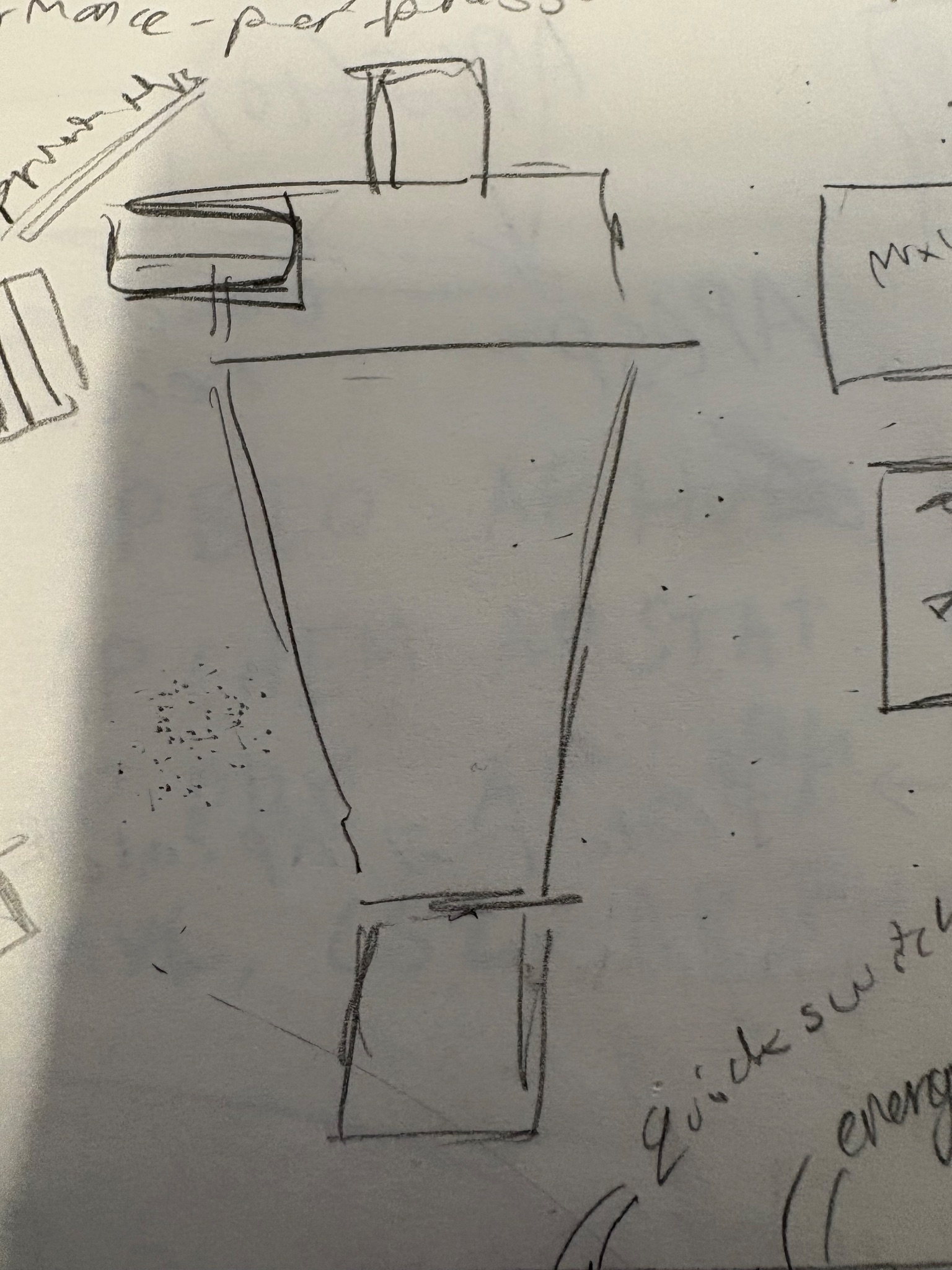
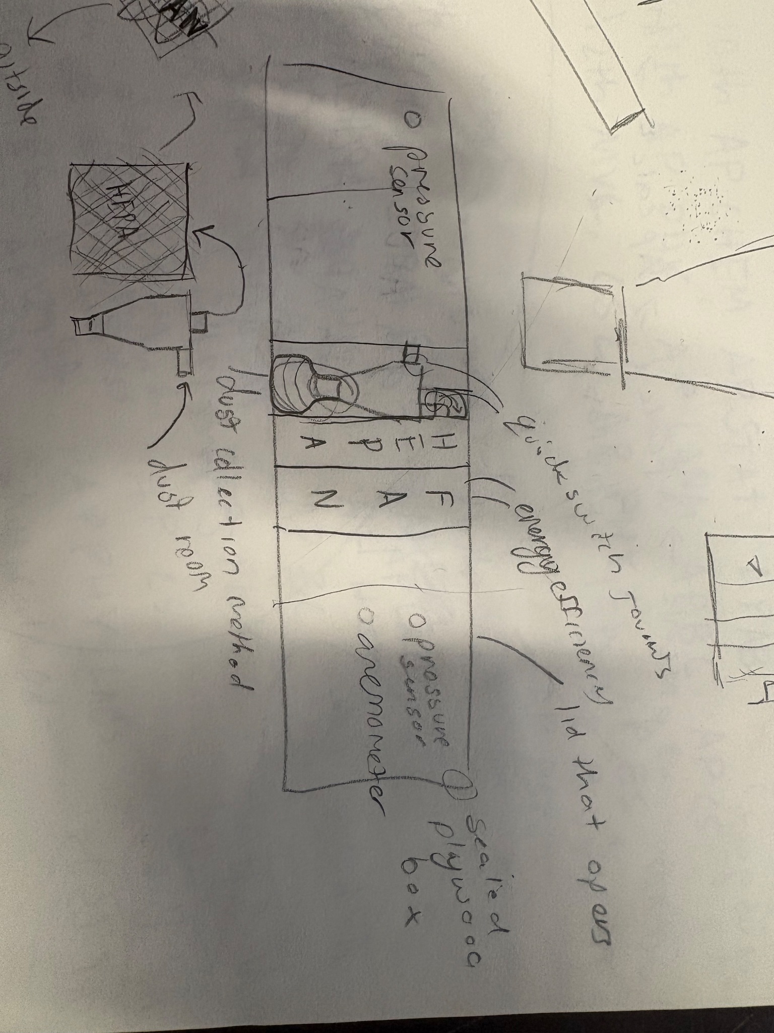
NEXT STEPS: Build an experiment around the idea of inertial prefilters
12 / 29 / 25: Created Bibliography
OBJECTIVE: I needed to build an experiment around this idea of inertial prefilters, so I decided I would choose three independent variables on a cyclone and see how they affected the ability of a cyclonic separator to act as a prefilter.
I researched on Google Scholar and found a few sources on cyclone separators: among which was the ‘Handbook of fluidization and fluid-particle systems.’ by Knowlton, T. M. This showed me how various variables impacted the cyclone. These are the ones I have chosen:
-
Vortex finder diameter: this directly controls the pressure drop of the system
-
Vortex finder Length: this is crucial in the separation efficiency of our system
-
Cyclone separator height: this is important for separation efficiency as well
-
Airflow : although not a variable I am changing, I kept this low since it affects vortex stability and air purifiers usually have a low fan speed.
I found a few more sources that helped me learn about these variables and made a small bibliography using them:
*Yohana, E., Tauviqirrahman, M., Putra, A. R., Diana, A. E., & Choi, K. H. (2018). Numerical analysis on the effect of the vortex finder diameter and the length of vortex limiter on the flow field and particle collection in a new cyclone separator. Cogent Engineering, 5(1). *https://doi.org/10.1080/23311916.2018.1562319
Knowlton, T. M. (2003). Cyclone separators. Handbook of fluidization and fluid-particle systems.
*Chen, Jihe & Jiang, Zhong-an & Chen, Jushi. (2018). Effect of Inlet Air Volumetric Flow Rate on the Performance of a Two-Stage Cyclone Separator. ACS Omega. 3. 13219-13226. 10.1021/acsomega.8b02043. *
*Hoffmann, AC & Groot, M. & Peng, W. & Dries, Huub & Kater, J.. (2001). Advantages and Risks in Increasing Cyclone Separator Length. AIChE Journal. 47. 2452 - 2460. 10.1002/aic.690471109. *
NEXT STEPS: develop a testing rig for this experiment and design it in Onshape
12 / 30 / 25: Started CAD for test rig.
OBJECTIVE: Develop a CAD design for running this experiment that includes all needed information in an easy-to-build form.
To test the cyclone separators we needed to know their pressure drop, their separation efficiency, and the filter loading. To do this I used CAD to design a complete rig that could include two pressure sensors (one for cyclone one for filter) and a removal dust collection bowl that could be weighed for finding collection efficiency.
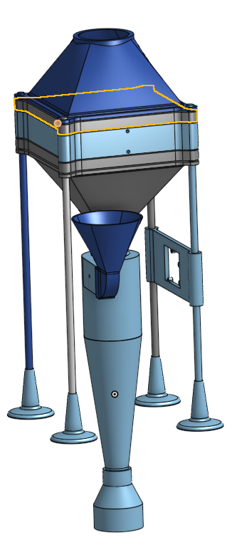
The rig is on top of four threaded rods, and will have a filter, two diffusers, a fan, and a cyclone sandwiched with nuts. Today I started by designing the diffusers and fan mount. My adult supervisor (my dad) helped me because he was a mechanical engineer, and was able to teach me how to use CAD in my design process.
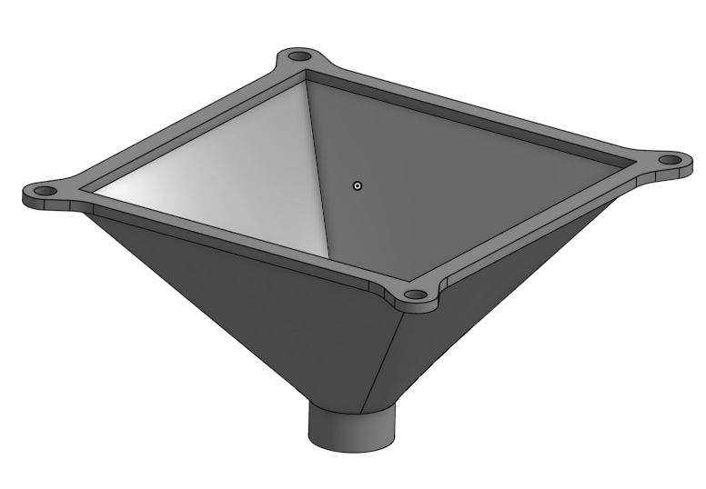
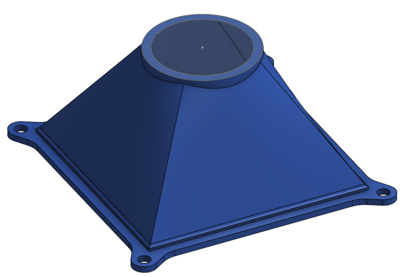
NEXT STEPS: Finish the CAD design and make list of materials to order
1 / 2 / 26: Finished Preliminary CAD and Made BOM
** OBJECTIVE: **Complete all the design for the CAD and make a bill of materials that we can order.
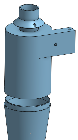
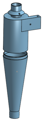
Today I finished the CAD for my test rig. The final design includes two diffusers, a cyclone, honeycomb patterns to straighten the flow, and a central filter unit. I removed the fan mount because they were unnecessary since I can just glue the fan onto the diffuser. The cyclone is split into three parts to minimize the number of wastage in filament. One part is the cone which is constant, and then there is a height section controlling cyclone height and a vortex finder piece that controls both the vortex finder diameter and depth.
Next, I will complete a bill of materials on all the parts I will need for this project. Some important parts are the MPX5010DP pressure sensors, the Arduino Uno, 0.01g digital scale, flour, baking soda, corn starch, holi powder, baby powder, centrifugal blower (fan), HEPA material, PETG filament, and PETF tape for airtight and removable joints around tubes.
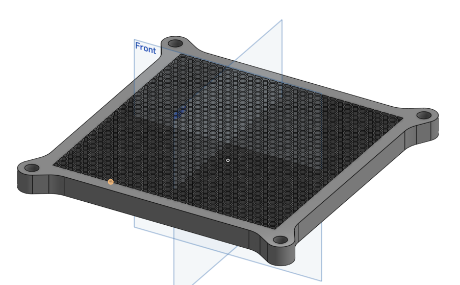
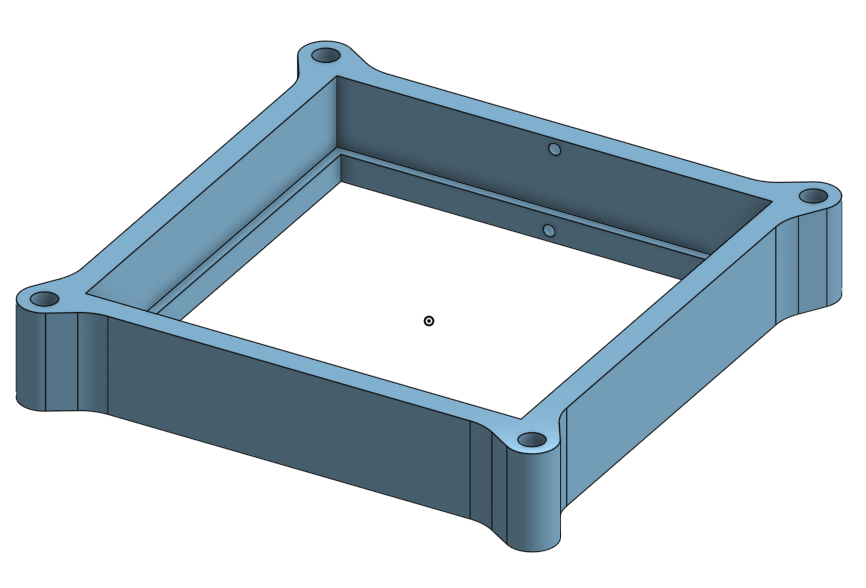
NEXT STEPS: Order all the materials and start working on the research plan.
1 / 3 / 26: Updated CAD and Ordered Materials
** OBJECTIVE: **buy all the parts required from reputable sellers. Update CAD so it is ready to print.
Today I bought all the parts from reputable sellers at Home Depot, Amazon, and Ali Express. They will arrive around 1 / 20, so this will be one of the last logs I am making for a while. I also updated some parts of the CAD to ensure they had enough clearances to fit and were designed to be easily 3d printed.
NEXT STEPS: Finish the research plan
1 / 7 / 26: Drafted Research Plan
** OBJECTIVE: **Finish the research plan and be specific and scientific in everything.
Today I started drafting my research plan for the science fair. I finished the rationale, where I explained the significance of my experiment and the personal reason for it. I also drafted sections of the research question, hypothesis, engineering goals, and expected outcomes. My mani question for the project was this:
How do vortex finder diameter, vortex finder depth, and cyclone height influence particle separation efficiency and pressure drop in residential air purifiers, and which combination provides the best trade-off?
-
*My main hypothesis for the project was this:
I believe increasing the height of the cyclone will increase particle separation efficiency by allowing longer particle residence time and stronger centrifugal forces to occur.
I believe reducing the vortex finder diameter will increase separation efficiency but also increase the pressure drop due to higher resistance to the airflow exiting the system.
I hypothesize that there exists an optimal vortex finder depth that minimizes short-circuiting (air bypassing the vortex and exiting the cyclone immediately). Extending below this depth, the vortex finder will increase pressure drop and break the vortex.
** NEXT STEPS: **Finish the research plan and print all the parts for the test rig.
1 / 10 / 26: Finished Research Plan
** OBJECTIVES: **Finish the research plan
Today I finished my research plan by adding the list of materials and procedures for my experiment. Creating the list of materials was easy since I had a BOM but the procedures were difficult because I had to be very specific and scientific in everything. I started by showing how I would use my five materials to test collection efficiency and pressure drop. I then talked about how to test the extension of the filter lifespan and the airflow testing.
After that, I showed my use of orthogonal arrays for the experiment. These arrays allow me to get the most information with the least amount of trials, which saves a lot of time and money.
**NEXT STEPS: **print all of the required parts and assemble the test rig.
1 / 15 / 26: 3D Printed Parts and revised CAD
** OBJECTIVES: **Print all the parts and apply postprocessing to make them suitable for experiment.
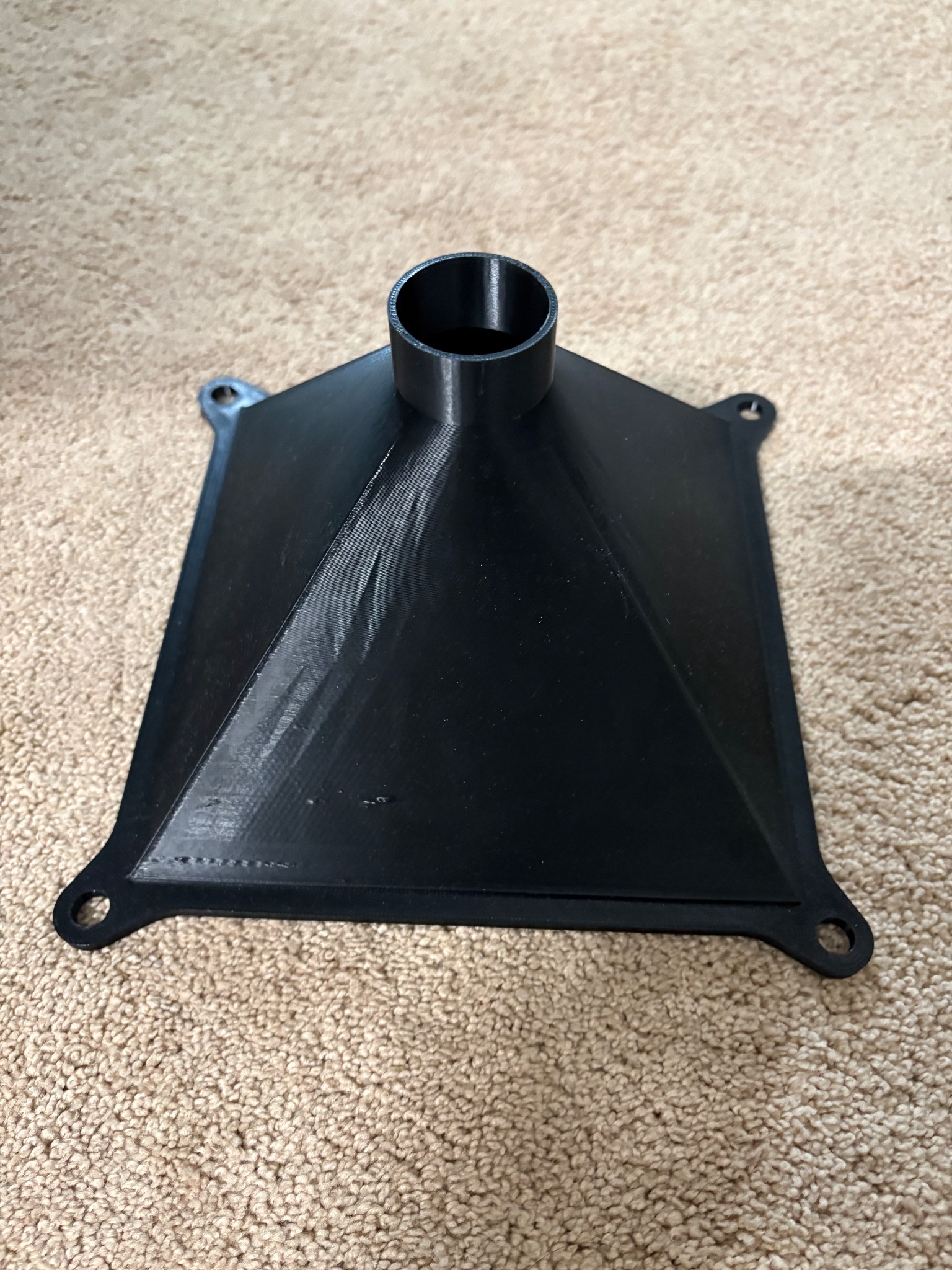
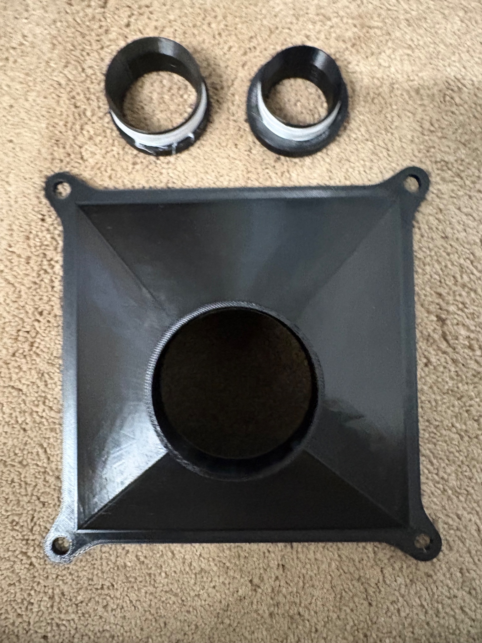
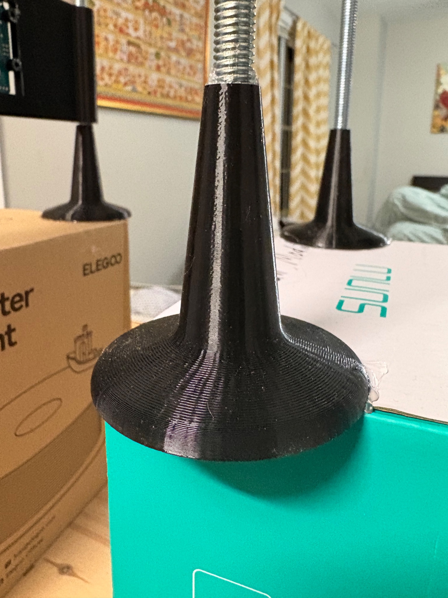
Today I 3D printed all of the parts for my testing rig using PETG filament, then sanding them with sandpaper and sealing them with CA glue to make them airtight. Below is a picture of all the different parts of the rig printing across multiple nights and days.
After I printed the cyclone I realised I had made a crucial mistake. I had made the diameter of the bottom diffuser fixed. This means even if I changed the diameter of the vortex finder, it would always be constricted here and ruin my experiment. I quickly updated the cad and made a new version that used multiple fittings so the diameter of the diffuser could be changed according to the cyclone vortex finder diameter.
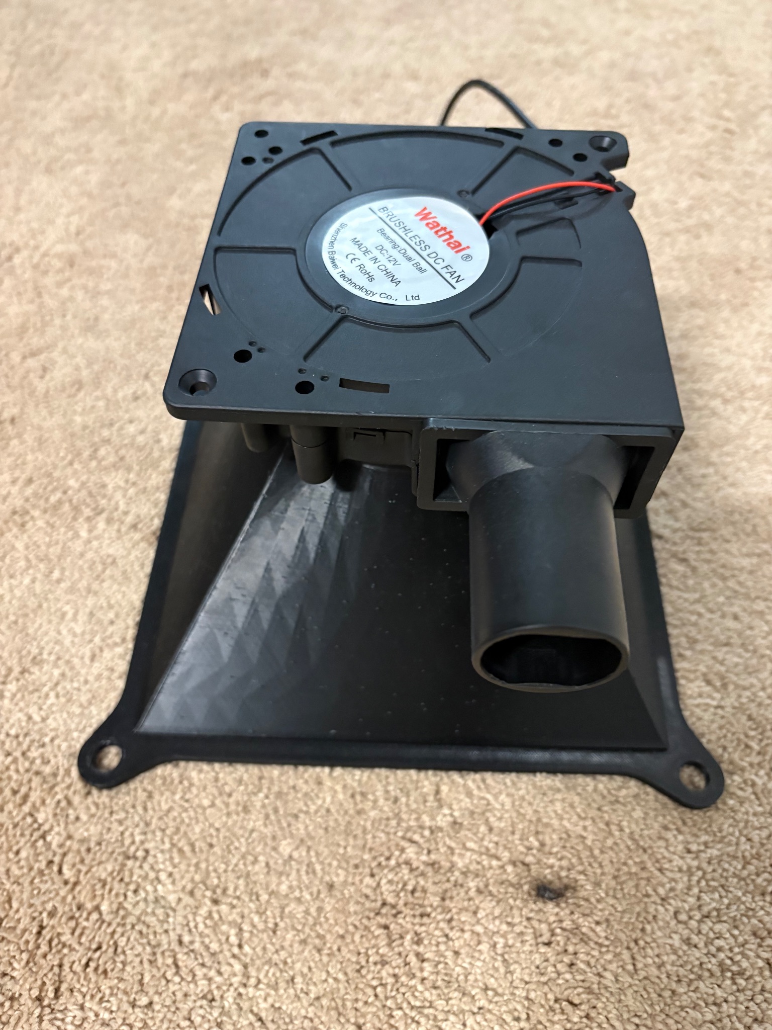
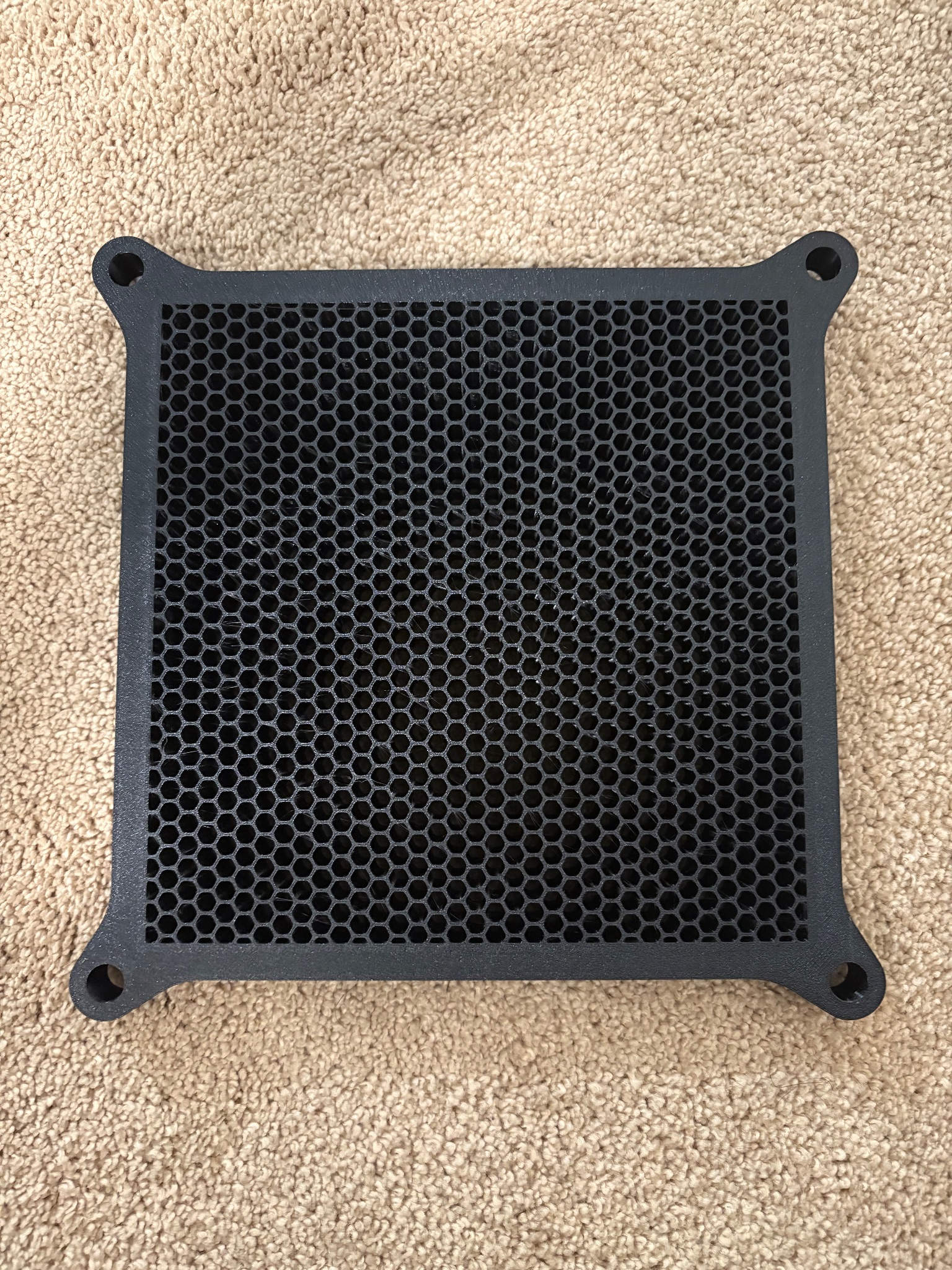
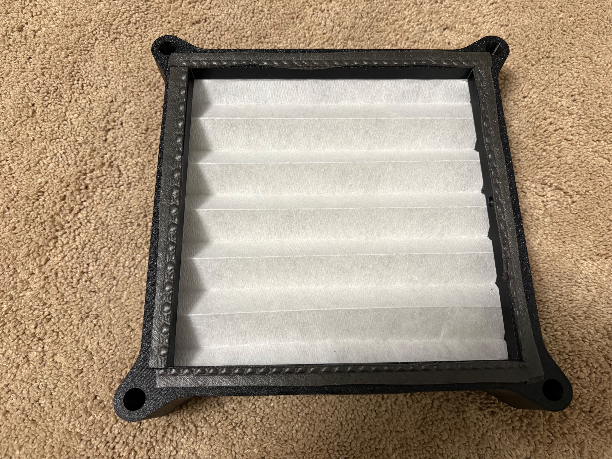
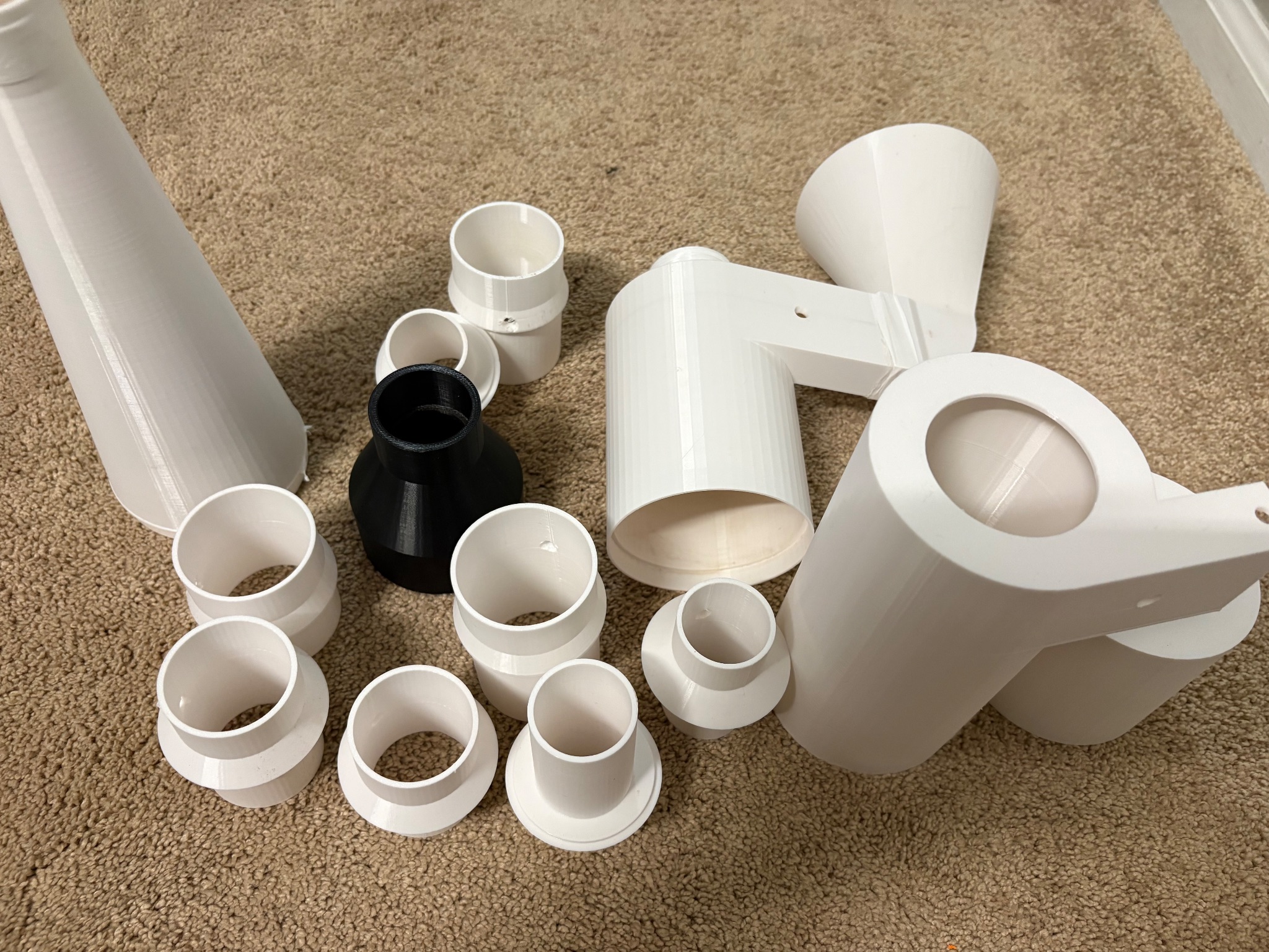
**NEXT STEPS: **Build the testing rig once all the materials arrive.
1 / 20 / 26: Received / Tested Ordered Parts
** OBJECTIVES: **Test all the ordered parts and make sure they work well
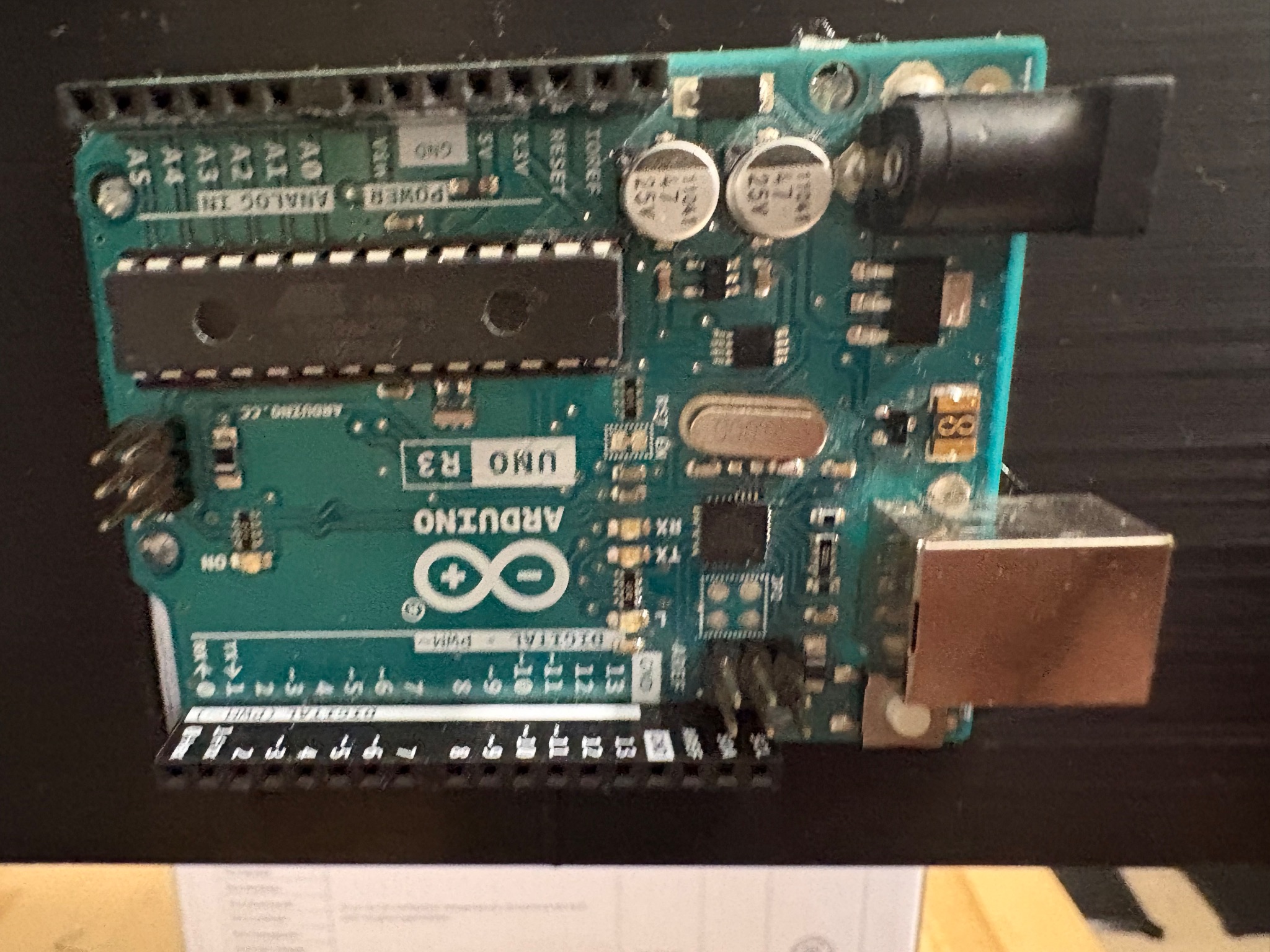
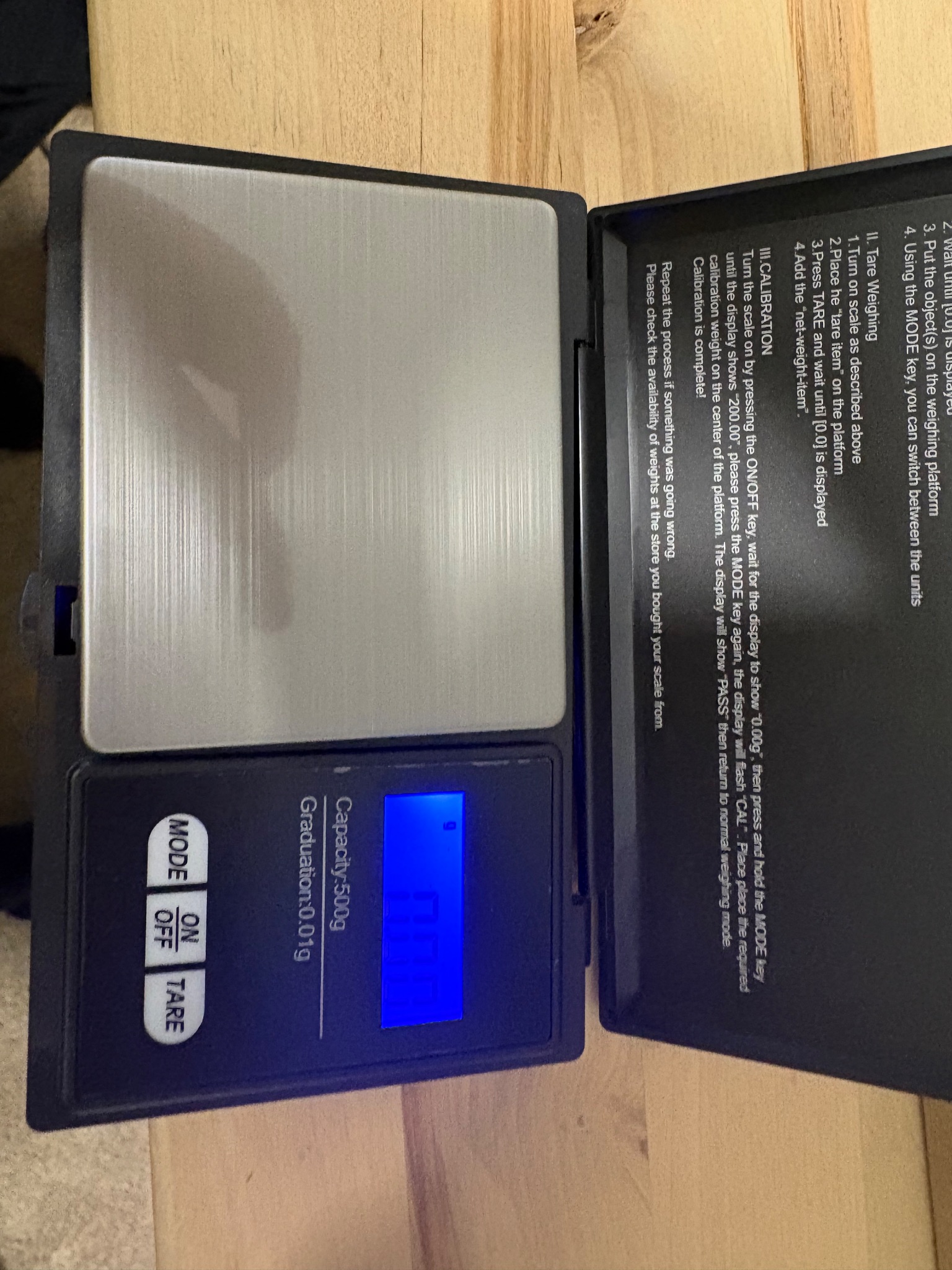
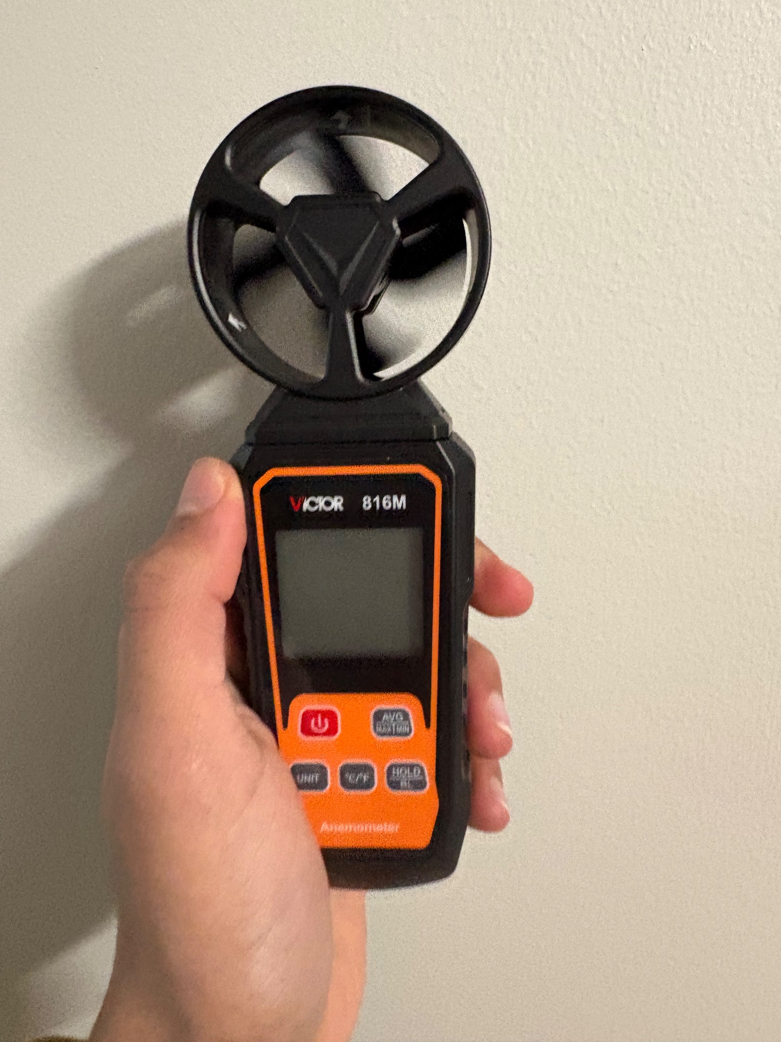
Today I received most of the parts for the experiment including my powders for testing, my arduino uno, my 0.01g digital scale, the centrifugal blower, my anemometer, the HEPA material, etc. I started testing the blower fan and found it was much more underpowered compared to what was listed on amazon. Fortunately, since I am testing my cyclone at lower airspeeds it had just enough power to generate a cyclone.
I also glued the HEPA material to the frame using airtight hotglue, and tested my anemometer to ensure it was taking accurate measurements. This was important so I could validate the airspeed of the fan across trials. One thing that did not arrive was the pressure sensors which were delayed from Jan 19 to Jan 25th.
** NEXT STEPS: **build the testing rig and test the cyclone
1 / 21 / 26: Change to Research Plan for Materials
** OBJECTIVE: **Find new materials to replace the bad ones we had earlier.
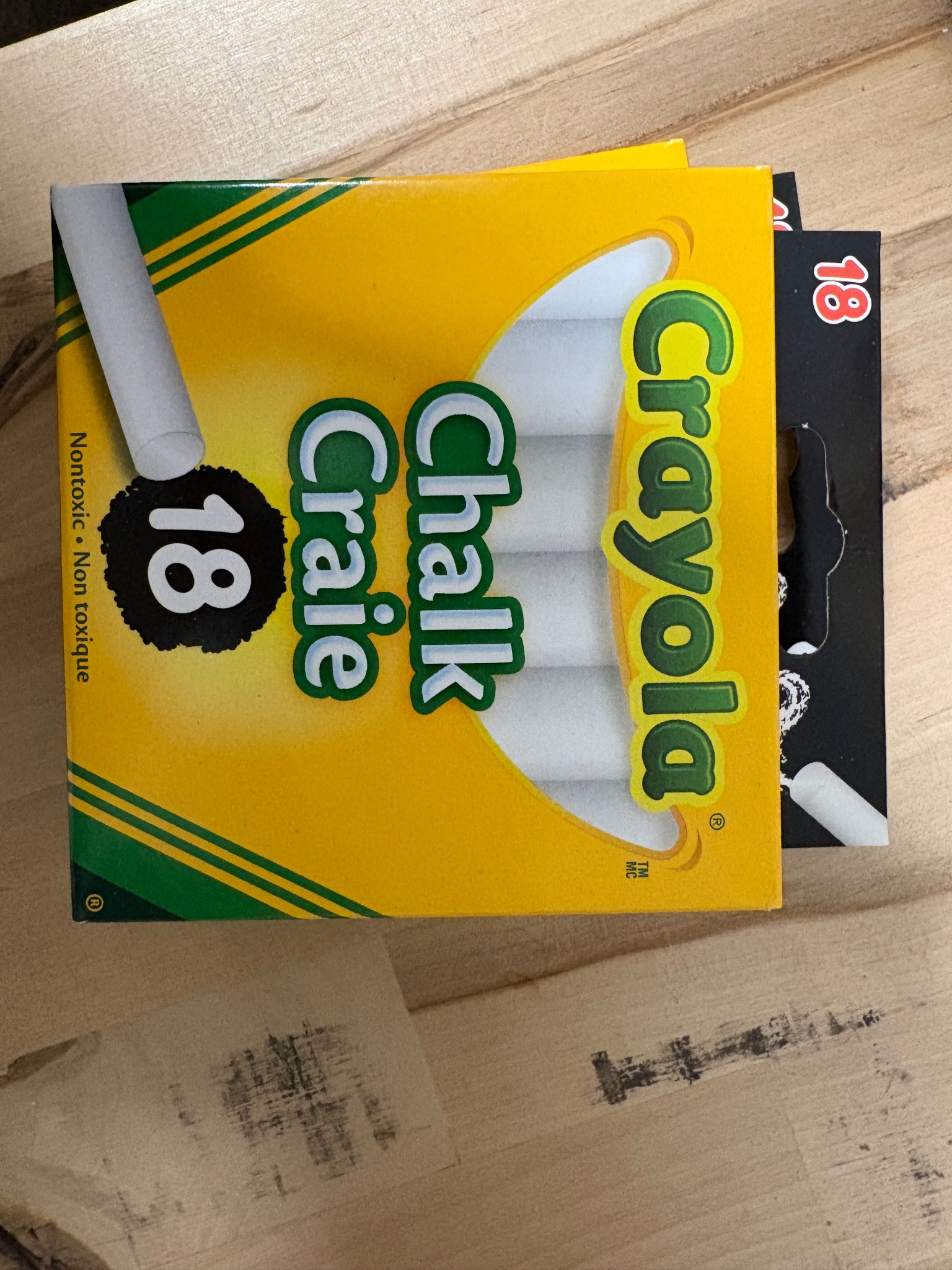
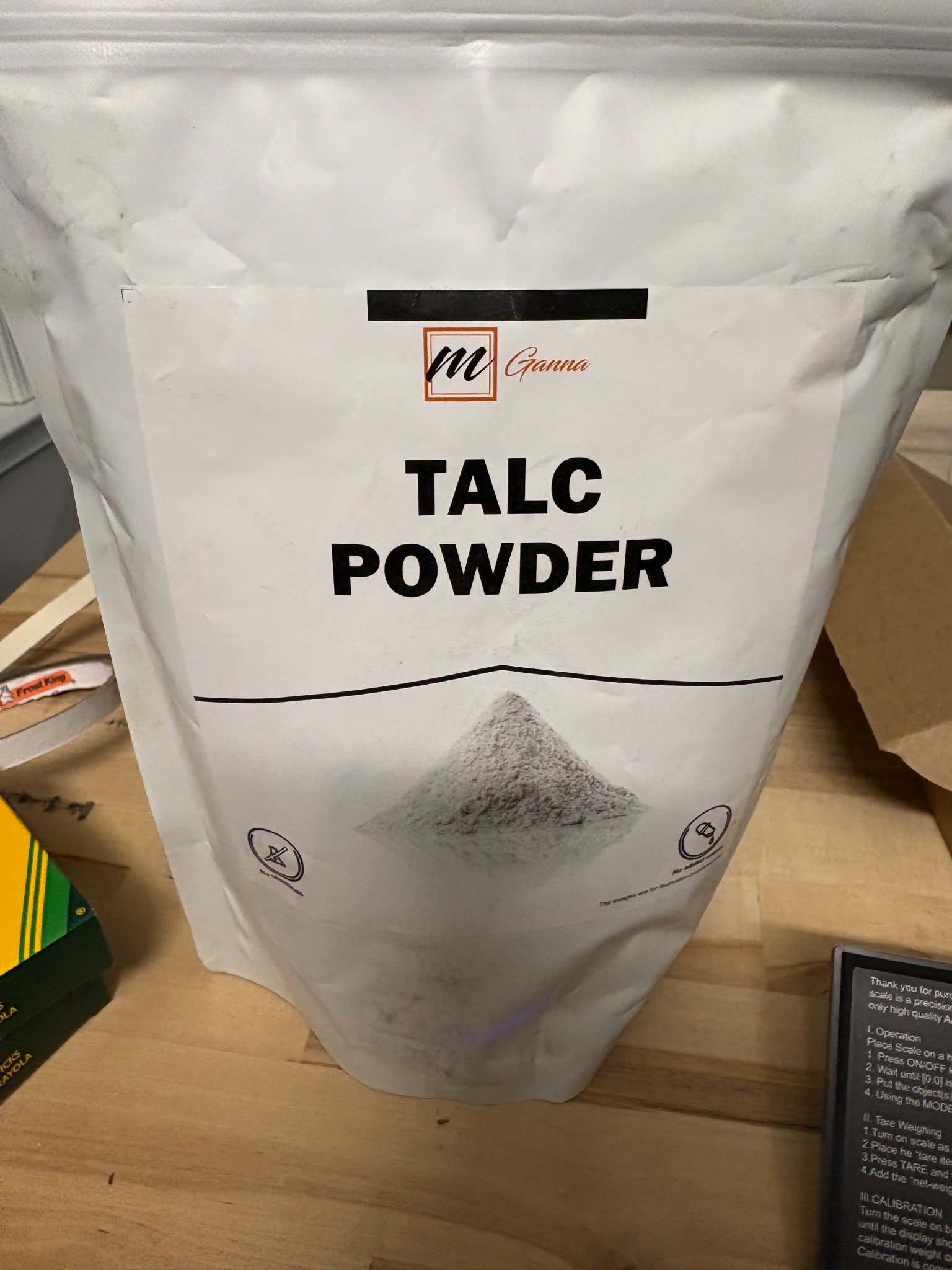
Today I made a shocking discovery. Original idea for dispensing the material (flour, baking soda, corn starch, holi powder, and baby powder) was a small funnel but since all of my powders were starchy, they clumped and bridged, making it extremely difficult for a consistent stream of powder to enter the airstream: crucial for pressure drop measurements. I realised I would have to choose dryer materials that would not clump and stick to the cyclone walls. I decided on using four alternative materials: fine table salt, baking soda, chalk dust, and talc powder. All of these materials are relatively dry and easy to source. They are also perfect for a range of values from 300 micrometers to <5 micrometers.
Additionally, I realised I could use an old electric toothbrush to vibrate the funnel, ensuring all the excess dust was disposed of into the airstream. I added all of these changes into an addendum for my research plan.
NEXT STEPS: Assemble the testing rig and test the cyclones
1 / 22 / 26: Assembled the final Test Rig with all Parts
** OBJECTIVES: **Assemble the testing rig
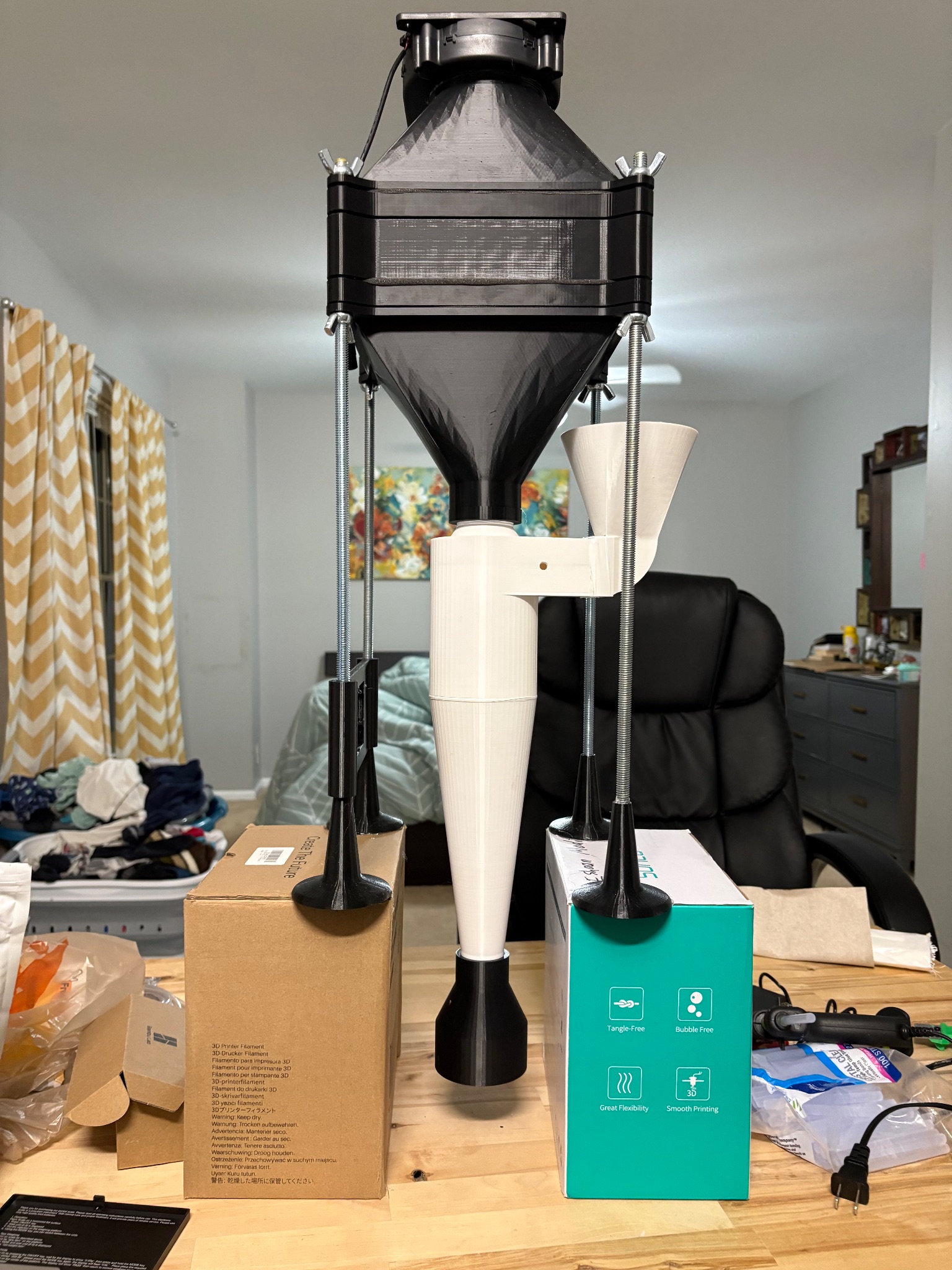
Today I assembled all of the parts I had into a nearly finished rig. First i used airtight hotglue to glue the centrifugal blower onto my top diffuser, and then i attached my arduino uno into my custom mount and clamped all five layers (diffuser 1, honeycomb 1, filter holder, honeycomb 2, diffuser 2) together using nuts with foam between them for an airtight seal.
I then wrapped the outside of my tubes with pet tape that kept my joints airtight and still reusable. Finally, I assembled the cyclone out of three parts using a mix of hot glue and PTFE tape. After I assembled everything, I turned on the fan and did my first test of my cyclone. For this I made the mistake of using cocoa powder. I thought it was similar to flour but would have a distinctive color that was easy to see, but I was wrong. Although my cyclone was clearly generating a vortex and filtered most of the powder, the oily, wet cocoa caked onto the 3d printed walls and was a mess to clean up. But, most importantly this showed my cyclone worked, but also that cyclones struggled with overly humid or only materials.
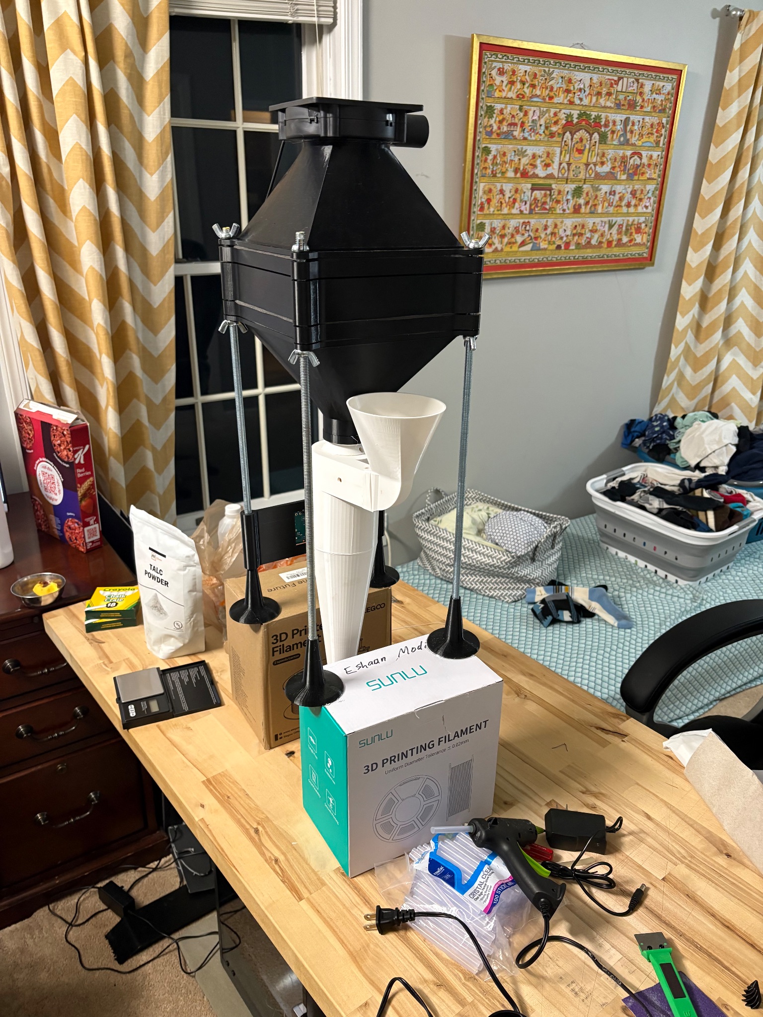
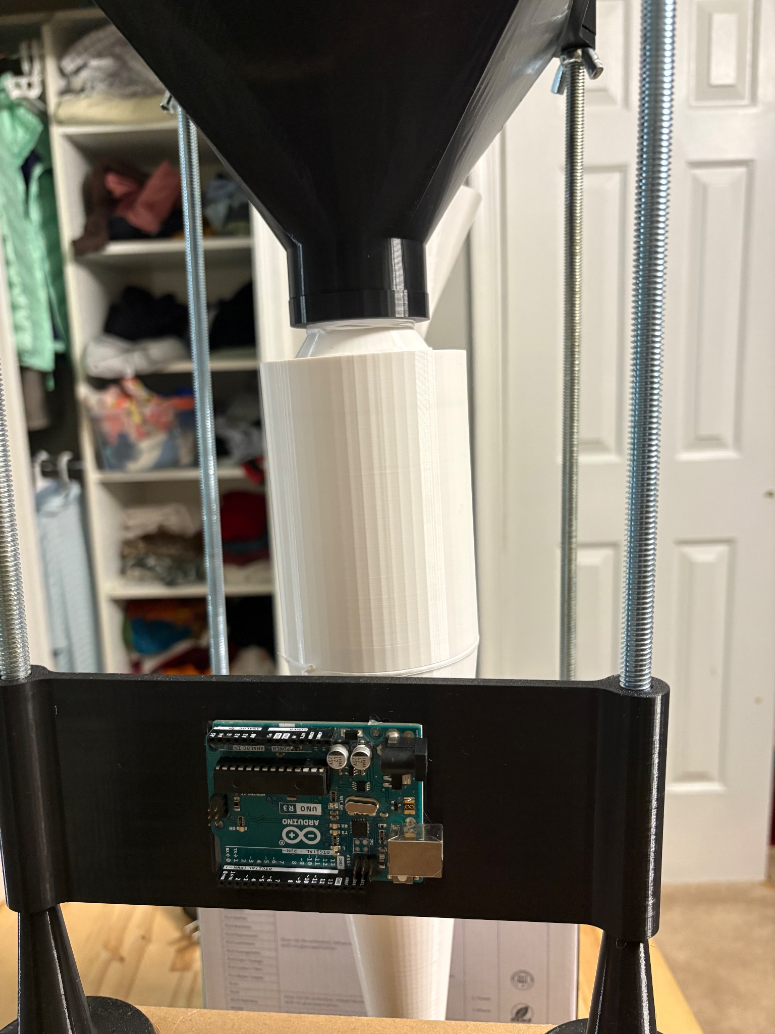
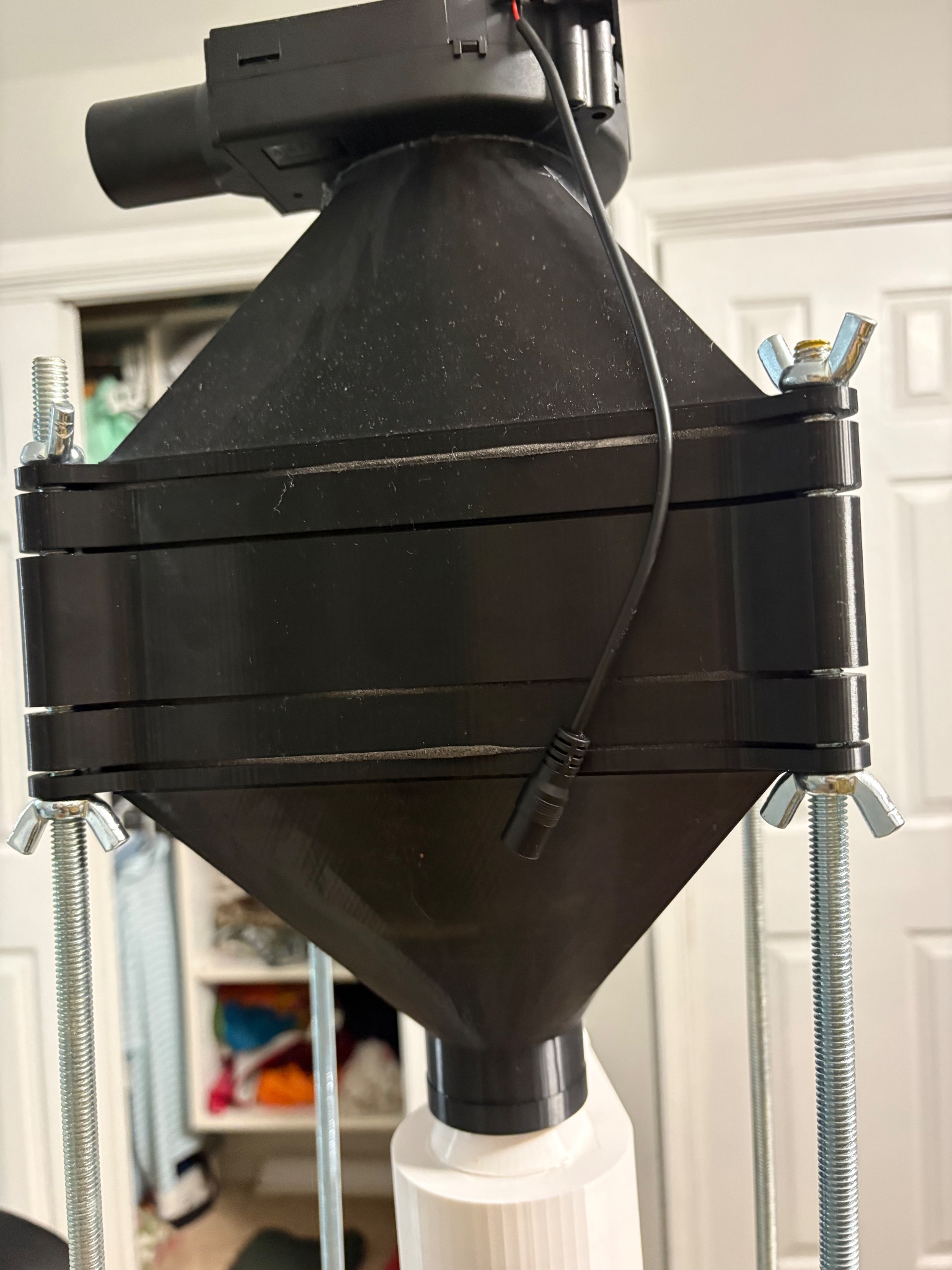
**NEXT STEPS: **Test the 9 different cyclone geometries and collect data once pressure sensors arrive.
1 / 24 / 26: Testing Day 1: started Stairmand cyclone testing
** OBJECTIVE**: Collect the efficiency data for all 9 cyclones in scientific way
Today I got the DPS sensors I needed to complete my rig and start testing. After ensuring the sensors worked, I connected one sensor across my cyclone to measure the pressure drop there. After I got my fan running at a stable 5 m/s, I measured the pressure drop across the standard stairmand cyclone and got a 215 pascal drop. I then started changing the fan speed to see how it affected the pressure drop. To my surprise, the pressure drop only changed by about 50 pascals: a miniscule amount. It should have changed by the square of the airspeed.
After thinking for some time, I realised that the reason this was happening could have been because I was measuring the airspeed at the centrifugal blower outlet, not the cyclone. I tried measuring the airspeed at the cyclone inlet and sure enough it was a very small number (around 1 m/s) from all the resistance from the cyclone and HEPA filter. That meant changing the speed of the fan did not have much of an effect on the cyclone.
Next I decided to try measuring some separation efficiency data for my base cyclone. I started with table salt, poured it in, and got a separation efficiency of 99.7%: expected for such large particle sizes. I next tried baking soda, and got 97.3%: also expected. Then the problems started to arise with chalk dust.
I had to use a mortar and pestle to grind my chalk sticks into dust which took a lot of time and effort. I also had problems with the dust sticking to printed walls which had picro grooves in them. In fact, the powder was stuck so tightly to the walls even my electric toothbrush i was using as a vibrator was struggling to pull it off.
Overall, the efficiency was 52.1% but I expect that much of the dust was stuck onto the cyclone walls and would have been collected.
Something else interesting i noticed was that i was originally going to measure the pressure drop while each material was going through the cyclone but after testing these three materials i did not find much variation (5 - 10 Pa) which shows that the particle loading was too low to make significant impact on the cyclone, since the airflow is more dominant in determining the pressure drop.
NEXT STEPS: Finish collecting the cyclone efficiency data
1 / 25 / 26: Testing Day 2: Noticed some problems with the testing
** OBJECTIVE**: Collect the remaining cyclone efficiency data and fix some problems with the test rig.
Today I tried testing the standard cyclone again for more accurate measurements. After retesting baking soda and salt, we got 100% both times. This was not hard to believe, but still surprising. After testing talcum powder and getting near 100 percent efficiency, I knew there was something wrong with my methodology.
Talcum powder is so small it should have been less than 80% accuracy at least for the cyclone. One thing I suspected was that the talcum powder was clumping. To combat this I may have to add some corn starch (<2%) that should minimize clumping.
Additionally, to minimize the static force that pulls the particles to the cyclone walls I wiped all surfaces with Isopropyl Alcohol.
The last thing I suspected was the problem was the airflow being too low, therefore not generating a strong enough vortex and letting the particles wall down from gravity. I will test a higher airspeed next time (5m/s - 8m/s)
I also got the pressure sensors calibrated and working, and found the pressure drop of the standard stairmand cyclone was 40 Pa.
**NEXT STEPS: **actually finish all the efficiency data.
1 / 26 / 26: Testing Day 3: finished collection efficiency for 10 cyclones
Today I finished all the pressure values for the 9 orthogonal array cyclones + the standard stairmand cyclone. One big change I had to make to the plan was only testing one type of material: talcum powder. This is because testing 4 materials for each cyclone would be very time intensive, salt and baking soda had near 100% capture efficiencies, and chalk powder was clumping and sticking too much. Here is the data I collected:
Cyclone Code
Nothing
Talc Powder
LLL
PD: 30 Pa
SE: 76.9%
LMM
PD: 24 Pa
SE: 73.6%
LHH
PD: 0 Pa
SE: 84.6%
MLM
PD: 5 Pa
SE: 79.6%
MMH
PD: 4 Pa
SE: 84.9%
MHL
PD: 1 Pa
SE: 80.1%
HLH
PD: 0 pa
SE: 86.5%
HML
PD: 2 Pa
SE: 90.3%
HHM
PD: 5 Pa
SE: 89.3%
STANDARD
PD: 40 pa
SE: 81.4%
As you can see the talc powder data looks fine, but the pressure drop data is inconsistent and inaccurate. Most values are around 0 Pa with a few that are 30 or 40 Pa. This does not align with results described in literature, as my cyclone should have around 100 Pa of pressure drop. I realized the placement of my taps (for the pressure sensors) was wrong as the air in that region would be turbulent.
The reason my tap placement is wrong is because one of my taps is connected to the vortex finder which is extremely turbulent. To combat this and read the correct pressure values tomorrow, I will place a tap further away from the main vortex finder.
**NEXT STEPS: **replace the taps and find the pressure drop of all the cyclones
1 / 28 / 26: Using DoE and Orthogonal Arrays for Optimized Cyclone
** OBJECTIVE: **Salvage experiment without pressure data and find optimized cyclone
Today I tried experimenting with different code and tap placements for the cyclone, but nothing seemed to be giving me accurate data. I decided to hold off the pressure sensor data collection until after the CCSRC fair because I was running out of time.
For right now, I used the taguchi method and found the mean values for all the variables when they were set to a specific level.
Height
VF Diameter
VF Depth
L: 78.37
L: 81.00
L: 82.43
M: 81.53
M: 82.93
M: 80.83
H: 88.70
H: 84.67
H: 85.33
** **This is the data I found and from looking at it, a high level for all three variables will give me the best result. I tested the HHH cyclone using the same procedure as the other 9 cyclones, and got a 88.84% efficiency, this is slightly less than the best cyclone from the 9 we tested (90.30%) but the difference is negligible. This shows us the taguchi method works well for finding the correct cyclone variant for maximum separation efficiency
**NEXT STEPS: **Run HEPA loading tests on HHH cyclone
1 / 30 / 26: Ran HEPA loading tests on Cyclones
** OBJECTIVE: **run HEPA loading tests on HHH cyclone
** **Today I ran the hepa loading tests once with the HHH cyclone and once without the HHH cyclone. For each test I replaced the hepa and added 5g of dust at a time, each time measuring the HEPA pressure drop (using pressure sensors) and the particle separation efficiency of the dose. I found something extremely interesting, the pressure drop started by increasing a lot but started leveling off around 250 Pa. Furthermore, the separation efficiency climbed from 10% to 90% over 7 trials, showing that the separation efficiency depended on the airflow of the HEPA filter (we were not correcting airflow using HEPA for this test because we just wanted to see trends across the bare HEPA.
Below are the two pressure drops to gram curves. The blue curve is without a cyclone and the red onesies with a cyclone. The green dots are the separation efficiencies of the cyclone.
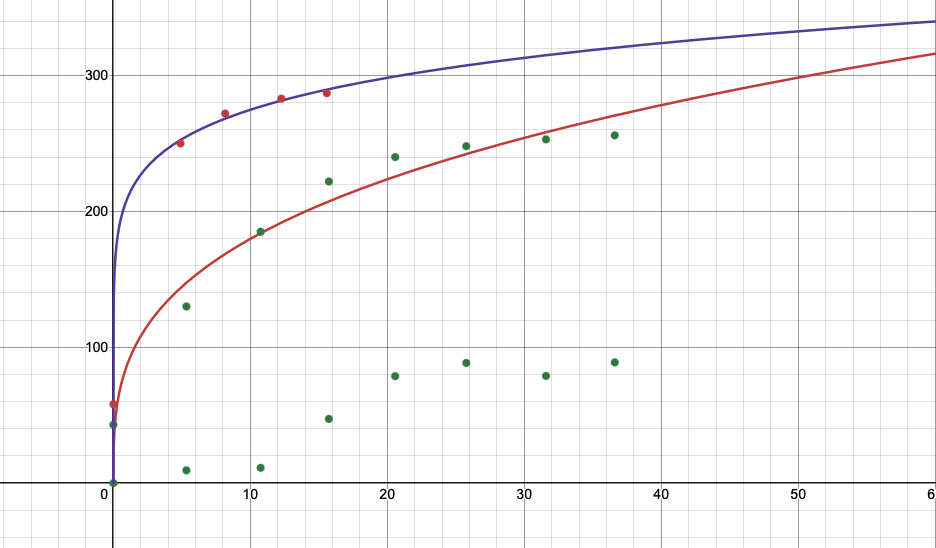 Further analysis of these numerical values was provided in the official project slides.
**NEXT STEPS: **Finish the slides and abstract
2 / 3 / 26: Wrote Abstract and Worked on Slides
**OBJECTIVE: **Finish all the slides and write a good abstract
Today I finished all my slides and wrote an abstract, I prepared all the paperwork and submitted the slides to the competition
**NEXT STEPS: **
- Finish the trifold and model for judging
- Prepare script and questions for judging
- Run pressure sensor tests if i can get the sensors working
- Run CFM analysis to see how it compares to real life results
- Run airflow analysis or test new materials with cyclones.
Indoor air pollution accounts for 3.8 million premature deaths annually. While air purifiers offer a solution, their filters need constant replacement raising cost and environmental waste.
This project investigates the use of cyclonic separators as reusable pre-stages for air purifiers.
The key research question was; “By what percentage can an optimized cyclone separator reduce the mass of particulate matter reaching a HEPA filter compared to a standard Stairmand cyclone design under the conditions of consumer air purifiers?”
I performed capture efficiency tests for 9 cyclone variants and used the taguchi method to find the optimal cyclone. I used this cyclone to perform HEPA efficiency tests.
I found from our experiments that using the optimized cyclone design allowed the HEPA filter to capture 6.3 times more dust before reaching the same pressure drop, suggesting a significant increase in HEPA lifetime.